![]()
![]()
|
|
| Over the course of several
months in 2013, Victor and Olga contacted me and asked all sorts of
questions about their Atlantic Clipper, 'Existence'. They are in
Croatia and are fitting her out for a long trip, the idea is to sail round
the world!
So the advice I gave was tempered with the thoughts that they may well be a long way from any boatyards and engineers, so we had to get this right. The first problem was how to remove the mast tabernacle to repair the cracks and twist in it.. I pointed them to the deckhead under the mast where they then found all the bolts securing it, the mizzen was more difficult however as the underside of the cabin top had been glassed over, them panelled... so it had to be repaired in situ. The problems he was having with the centre board and the experiences of others, the remarks by Maurice years ago, saying he was 'unhappy' with the way the original 'L' shaped plate had been replaced with what he considered an un seamanlike plate, made me advise the sealing of the slot and removal of the plate altogether. This Victor has done. They had no idea how the boats prop shaft was sealed, but the stern gear was a standard sort of prop stern tube with bolt down stuffing box and bearings, so I could advise on that, but the outboard bearing was different and though I could advise about how to take the fitting off, I then spotted what looked to me like an outer stuffing gland, which is just what it proved to be, not many have ever seen one, but luckily I had been shipmates with one. Designed to protect the shaft bearings in silty waters. Not what I would expect him to have to sail in whilst girdling the planet! So a replacement plain water lubricated tuphnol or special plastic bearing was needed. Job for Norris's of Isleworth or the like! I am pleased to say Victor has collated all the mails and made up an article as a result, here it is! John
|
|
The Restoration of 'Existence' |
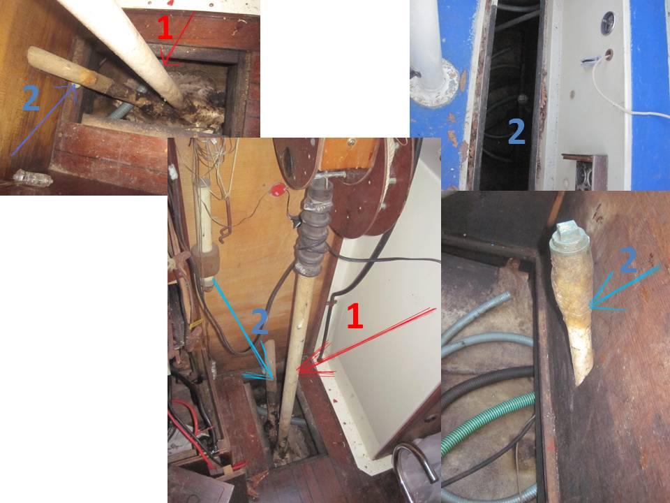
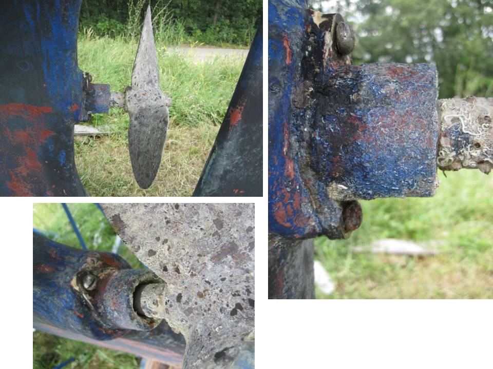
We decided to remove the drop keel board in order to improve the seaworthiness of the vessel, since there had been cases when this board caused significant leakage inside the boat. Therefore we sawed off the tubes holding the keel board rope (picture 1),
the rest of the tubes was filled with fixing foam and the top was glassed over with epoxy tar, afterwards we are going to paint that with primer (picture 2).
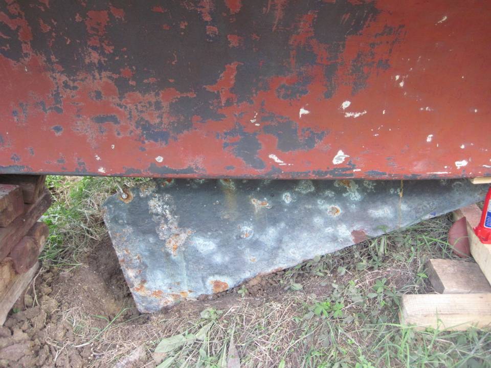
In our case we had difficulties in taking out the keel board from the well (picture 3),
that’s why we used the disk saw to remove that part of the board, which would come out of the well. After that we cleaned the well from accumulated shells (picture 4)
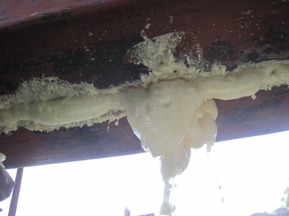
and filled it with fixing foam, evenly cutting it along the bottom line when it hardened (picture 5 and 6).
The next step was to glass it all over with epoxy tar and glass fibre and paint it with osmosis-curing primer along with the rest of the underwater part of the boat. Has anyone else tackled this differently? Would be interesting to hear how you got on. John
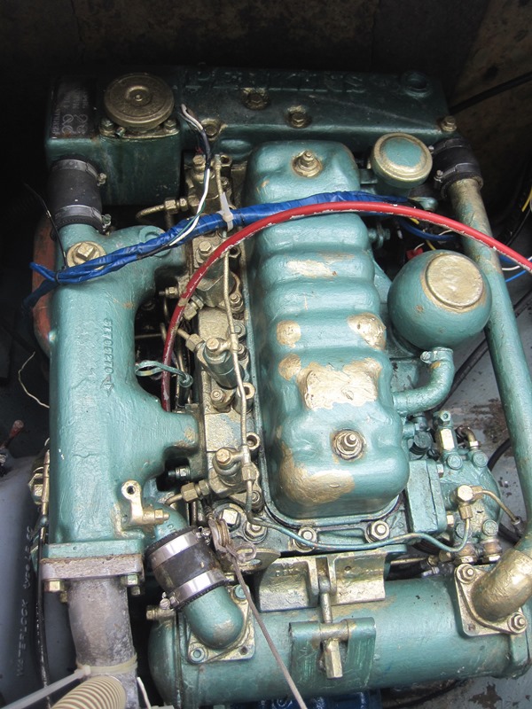
We took off the cover of the cylinder head and adjusted the valve gaps. After that cleaned everything we could, covered with primer and respective paint. Later we will change the oil and will hope that this is everything, that a 40-year-old English Perkins would require… I think, there’s some sense in changing the transmission oil as well! Would certainly advise changing the oil in that gearbox! should be changes, as the engine oil and filters every 500 hour use or as directed by the engine manufacturers. John
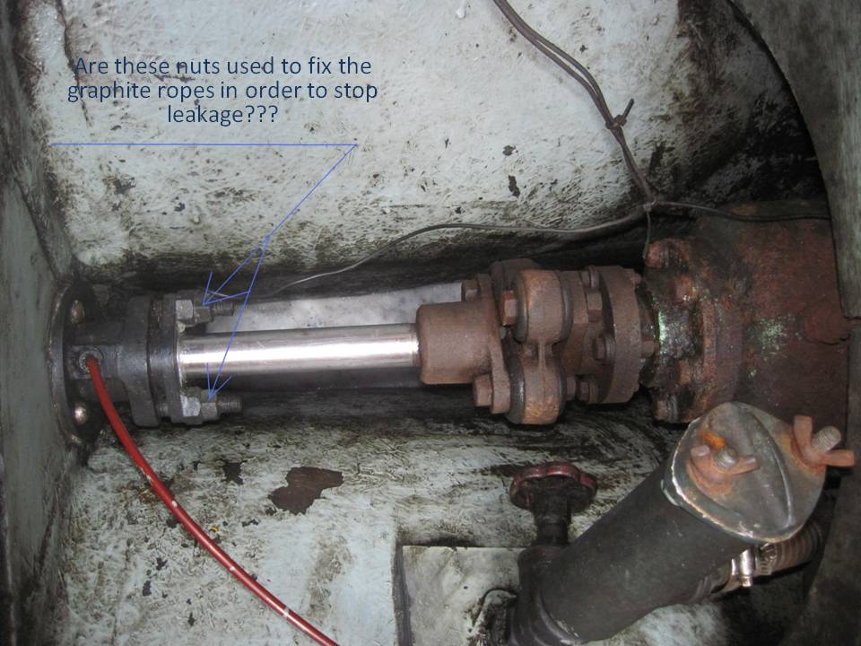
While the boat was afloat, we noticed that
there was a significant drop-by-drop leakage to the bilge from the
propeller shaft, therefore as soon as vessel was ashore, we decided to
eliminate the cause of this leakage. The opposite end of the propeller
shaft comes out in the aft cabin and looks like this (picture 9).
The propeller is to the left and the engine
is to the right. The shaft is sealed with a number of graphite rope
rings (6.6 mm each), which are really worn out. In order to change them,
we had to unscrew the cover fixed by holding screws (picture 10).
We ordered the new graphite rope in the
shop and are going to take out the old one with something sharp, after
that we’ll cut the new rings as follows -carefully placing the rope
around the shaft, we will make a 45 degree cut. When putting the new
rings in place, we’ll make sure that the cut of each ring is in a
different position in respect to other rings, in order to prevent the
leakage through these cuts. After that we will tighten the cover with
the nuts as parallel as we can. Further on we are going to turn the
shaft by hand and tighten the nuts further to the extent, when the shaft
is turned with a little but harder effort. If there’s still a leakage
when the boat will be afloat, we’ll continue to tighten the nuts until
it’s gone (normally, no leakage when the shaft is not rotating, and a
couple of drops per minute when the propeller is spinning). The alternative might be to invest in one
of the more elaborate stern tube seals, I have a 'Deep Sea Seal' on
mine, but as spares in far flung corners of the world would be
difficult, keeping it as near standard as possible makes sense. John
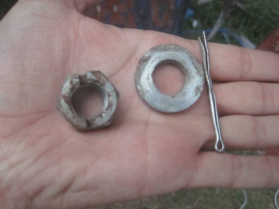
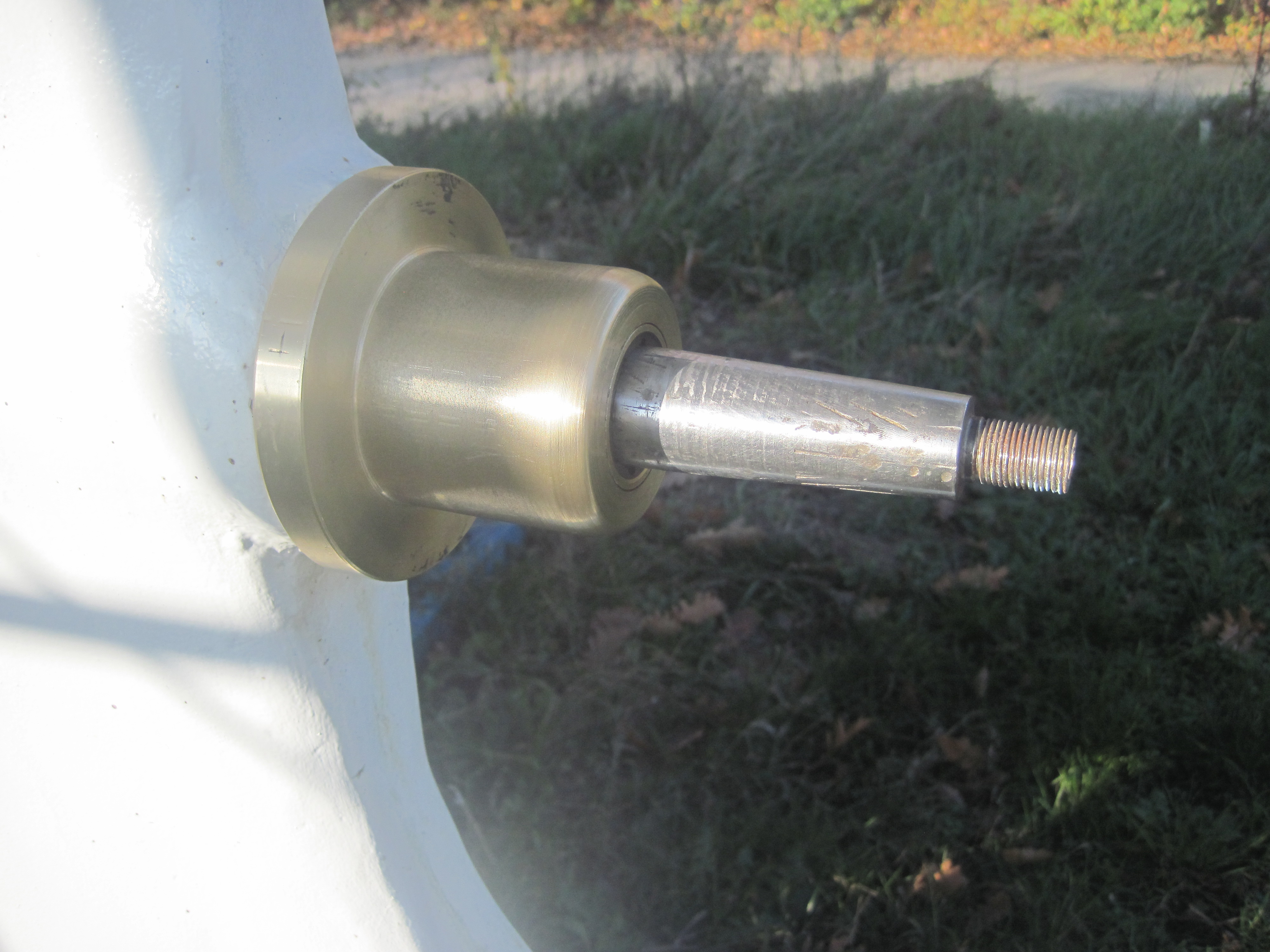
From the outer side
the side-to-side movement of the propeller shaft is restrained by a
water-greased sliding bearing. In our case we have the side-to-side
movement of up to 3mm, which definitely speaks up for changing the old
bearing. In order to take off the holder of the bearing we had to take
out the pin and unscrew the nut with the washer, which fixes the
propeller (picture 12 and 13).
Probably that was the
first time in 40 years when the propeller was removed, that’s why we had
to use a special remover in order to pull the propeller off the shaft
(picture 14).
We sprayed WD 40
everywhere and waited for 3 days, gradually tightening the bolt of the
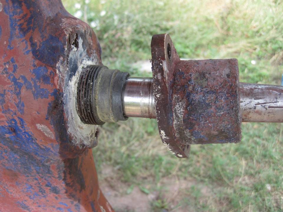
remover. After that the propeller went off the shaft. Here we come with the
bearing holder (picture 15).
In order to take it
off, we unscrewed 2 locking bolts, which were right in the plastic of
the stern, and by applying lightly a large spanner, unscrewed the holder
itself from the stern tube (picture 16).
As a result, we have
a holder, the bearing is inside (the outer diameter is 49mm, the inner
diameter 31.5 mm, 6 mm wide), which is gripped by two copper washes
(picture 17 and picture 18)
and the locking ring
(picture 19).
The bearing itself
looks like it’s made of some kind of a fabric and copper springs. I
doubt that we can find something like that now, so we’ll have to inquire
from the engineers around – they say now there are some new kinds of
material for water-greased bearings (e.g. tuphnol). As soon as we find
something to replace the old bearing, we’ll put everything back as it
used to be! Hopefully Victor will
be able to source a suitable outer bearing, it does not want to be a
cutlass type fluted rubber one, as there are no 'ears' on the outer
bearing holder, but of course there is nothing to prevent him from
replacing that outer bearing holder with a cutlass one, if he cannot
find a water lubricated Tuphnol or modern plastic one, that would be a
good answer. bet the stern tube thread is a standard one. John
When taking down the mast, we accidentally
damaged the mast tabernacle (picture 20),
so it was necessary to straight and weld
it. Since welding metal right on the plastic does not seem a very good
idea, we decided to take off the tabernacles. For that we dismantled the
ceiling of the saloon to unscrew the nuts, which held the bolts from the
inner side of the boat (picture 21).
However we were not so successful with the
mizzen tabernacle (it looks as if in order to remove it, we have to take
down almost all the panelling of the aft cabin) – so we’ll try to weld
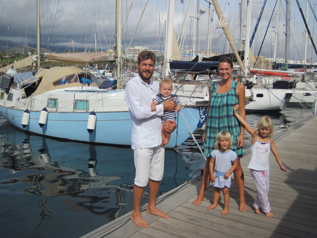
the small crack in it right on the boat... While wife and I are sweating over the
boat, the kids pick up vitamins! (picture 22)
Ours are not quite ready yet and smaller
than those berries! John, September 2013
When we first examined the underwater part of the boat on the shore, we found one large and soft bubble and opened that with a knife (picture 24).
This is osmosis. We thoroughly cleaned this place with an angle grinder, then with a large polishing disk, then covered it with osmosis-curing primer, puttied that with epoxy filler and glassed over to the level of the rest of the board. After that we peeled all the anti-fouling paint and painted the underwater part with 10 layers of osmosis-curing primer (picture 25).
So with that we deem the underwater part of works to be completed! Victor. Anyone else had osmosis problems with an Atlantic Clipper? John
|
| Sure
you will agree that Victor Olga and family are making good progress!
hope to be able to assist them further as they fit 'Existence' out for the
long trip! looking forward to more text and pictures to add to their
page! John |
| No sooner written this than
Victor comes back with another problem. how to get the U/S bearing out
of the outer end of the tube. Now when he sent this picture in I have
to admit to never having seen a bearing jammed up the tube like this
before...
Hello, dear John! Normally the bearing, be it tuphnol or plastic or a water flushed Cutlass ? Cutless! (Both correct I am told). so how to get it out? The only way I can see is to remove the shaft then with a hacksaw make 2 cuts into the bearing and allow it to collapse. I searched and found that this was exactly what the 'experts' recommend.
When cutting into the bearing you may just nick the tube, but this should not matter. Once cut, the old parts will fall out. I then thought about it and feel the best way forward at this stage would be to replace the outer bearing holder with a Cutlass bearing holder, as below. these are available at Norris's of Isleworth or many other stern gear specialists.
These pics show the outer bearing holder for a Cutless/Cutlass bearing with the 2 ears on the housing to direct water into the bearing so grit 'cuts the shaft less'. All the rubber Cutlass bearing in in the holder, and nothing up the shaft. I am sure this arrangement would be more easily maintained and parts are universally available, so more suitable when planning this sort of long trip. We will see how Victor gets on. John |
|
|
|
Thanks
a lot for the information and the links, we've studied thoroughly all
possibilities and have some ideas, which need your consideration! The first thing is that we are terrified by the challenge, which is the shaft removal, since we have to take out not only the shaft, but also the steering first! (see the pictures on steering). What kind of job is it??? Could you give us a short description on how the steering is removed and how then we take out the shaft? Since we don't understand this process and suspect that this can be a tough job, we are looking for other ways to renew the bearing. And thanks to your last message we had the following thought. What if we leave the old bearing as it is and just buy a new bearing housing instead of our current holder, which only houses the sealing ring, with a cutless bearing about 5 cm long? What do you think, how it would affect the performance of the system (the bearing will be relatively short and located at the very end of the shaft)? Will it work for some reasonable time? Is it reliable? And one more idea. We've just heard from a friend, that in case you cannot remove the shaft or the old bearing, so called "liquid metal" can be used.
This is some kind of
mixture based on epoxy tar, and they say, it can be filled in between the
old bearing and the shaft and in 15 minutes it's hardened, but it does not
stick to the shaft. So in effect, it will act as a new bearing. Have you
heard anything about that??? Hello Victor, That steering arrangement looks pretty permanent! I would have expected to see a way of removing the rudder to service it. I am not familiar with the Atlantic Clipper steering. Very often boats have a bottom bearing that is bolted to the skeg, and removal of this enables the rudder to be un bolted inside the boat and dropped down. Some may have a flange just above the blade and the rudder shaft has a matching flange and 4 bolts, there is nothing like that on yours. There has to be a similar stuffing box and bearing arrangement on the rudder and that has to be 100% before setting off on a trip such as you contemplate so it does all need checking out. However unless there is some means of removing the blade that I cannot see it rather looks like it was put in place and a boat built round it, most odd! The only other way of removing the shaft would he if there was a cut out in the rudder to enable the shaft to pass, seen than on some boats. Failing that the shaft has to be extracted by moving the main engine and taking the shaft inside!!! A major job. If the shaft rotates OK in the tube and that ‘bearing’ cannot be withdrawn and replaced you will have to look to an alternative. A new outboard bearing holder with either a cutlass or tuphnol bearing may be the answer, just leaving the old ‘bearing’ in the tube. ( I would be very interested in knowing how that bearing was fitted and how the maker thought it could be serviced!!) Without drawing the shaft it is impossible to know…. I have not had any experience of the epoxy bearing material, but I would suggest that unless all scrupulously clean you may find difficulty getting the epoxy to stick to the bearing holder. Sounds as if you may have to take local advice on this one!
I wonder if anyone reading this has any suggestions. John
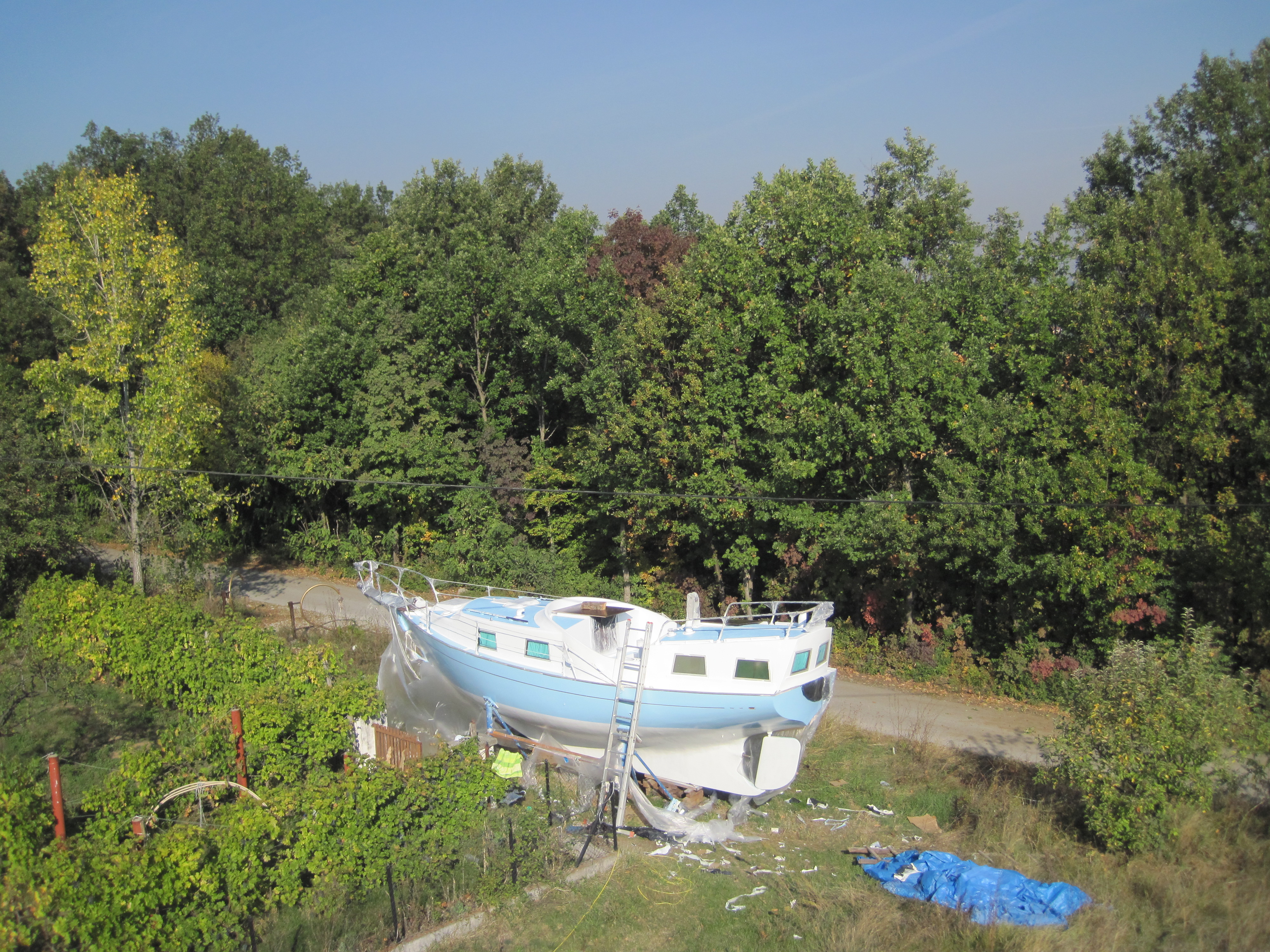
October 2013, freshly repainted! October 2013. Victor has another problem....
The major thing we’ve been dealing with during the last 2 days is the steering mechanism, I’ve greased and painted all the important joints and added 2 more rings of graphite rope (picture 94, 95)
. However I encountered an unexpected problem when I tried to get inside the column, which holds the steering wheel (picture 91). I decided to go inside, since I hear some kind of slight rattling when I turn the wheel. So when I tried to remove the wheel holder plate by unwinding 4 screws, it didn’t move. I tried to move it slightly with a small screwdriver and a tiny hammer from the side, since I thought that the metal is just old. But it suddenly went off and I saw that it broke up, leaving the inside part of the plate in place. This detail is on the picture 92. So on the picture 91 you can see the rest of the broken part, which is marked by the red arrow. I had a cowardly thought that maybe I can leave it that way, but probably it’s not a good idea, because it might hold some kind of a protecting ring, same as I had on the propeller shaft. In this respect we are now guessing whether there can be a threading inside and we should try to unwind the rest of the broken part, or it does not have any threading at all? Do you happen to know this?
Victor. Hello Victor,
The steering pedestal looks to be very corroded at the point the shaft emerges. It is going to be quite difficult to remove the remains of the cover plate, but I bet you are going to have to, just to ensure all is safe…
I do not know this gear but imagine there must be a way of lubricating it and a seal of some kind there. Without a makers name it may be difficult to find out what make it was. Maybe one of the other owners may able to assist with a makers name!
Steering pedestals often have gears at the top and a shaft drive, but some have a cog and a special chain drive, either way I would like to see what was in there and what condition it is in. It is every skippers nightmare to lose the steering. Is there an emergency steering arrangement? John November 2013. Hello, John! Writing to you with our updates – we were able to pull out the stuck part with some homemade device! Now I can see all the mechanisms inside and can service them properly. There were indeed some places much prone to water ingress, which I treated with epoxy filler. Now just have to grease everything and order a new bronze part instead of the broken one, and believe this steering is to be reliable for some more years. At least I know now, how it’s all organized, this is the most important thing I believe. We also made a new housing and placed there a half of the cutlass bearing, it is now screwed on the outside of the shaft. Maybe can make something with the old inside bearing as well. Have to think about that! We hope everything is fine with you and wish you a beautiful and peaceful winter! This is the only time of the year, when one can sit in front of the fire and spend some time thinking of who he really is and what this life is all about! Kindest regards, Olga & Victor Very pleased to hear that Victor managed to take the steering gear apart and is now able to check and service it, a very important issue when setting off on a grand trip such as he is intending. all in all every part he has attacked has been restored back as new, Very well done Victor a high standard indeed! We must thank him for sharing all this with us as now other clipper owners facing similar problems will have most of the answers! John June 2014.
Dear John! https://www.youtube.com/watch?v=ZmK3X-FiCGc&feature=youtu.be Edited link now works!
Victor posed an interesting question. Now he is afloat he is considering replacing the aging inboard diesel with an electric motor? Any one have any experience of these? To my mind I always worry about electrical items on board, they have to be so well made, (and therefore expensive!) to resist water and the associated corrosion. On the other hand I bet we have all seen inboards mouldering in rust and exposed to the elements and still plodding on many years after they should have been consigned to the deep as mooring weights! (properly degreased of course) . I think I would always rely on a diesel and if based on a common motor, say a Ford, parts will be available anywhere. A more pressing problem, for anyone contemplating a long ocean cruise as Victor and Olga and family are, would be that water tank. Can it be cut out and replaced? Can he get to it? I would be inclined to remove it, even if it meant cutting it up, and replacing with either a ply and epoxy built tank or tanks or purpose made smaller multiple stainless ones. That way you could plumb them in to be separate in case there was a contamination problem, or another leak... Sure Victor will sort it! John
September 2014
Hello dear John! Well done to the pair of you, and the family, we look forward to the log to add to the new logs page. Your problems with the engine are sad, there must always be a loop in the exhaust to take it well above the waterline, before it falls to the outlet, however it is sailed and a water lock for the water in the first part of the hose and an anti siphon in the water injection. These are basic ways of installing a motor but sadly often ignored. A dear friend and member of the group has had the same problem with one of the two new 10hp motors in his catamaran. All the pipes were fitted correctly, I know I fitted them, but sadly the anti siphon was blocked as it was one of the Vetus auto siphons and it leaked.... will cost him dearly. I suspect he will be removing the auto part and replacing it with a plastic hose, the end left in air draining into a cockpit drain. I have this set up having removed my auto siphon years ago, it dribbles into the cockpit drain by my feet when I am motoring and am on the helm, a good indicator that the water is flowing, as well as the splashes from the exhaust outlet... We look forward to seeing that log! John
Hello, our dear John!
John
Hello, John!
Congratulations to the Existence racing team, transatlantic sailors!
John March 2013 and she is up for sale as they look for a larger craft to carry them further!
SOLD December 2015.
And we hear
they have given up boating and gone to Russia.
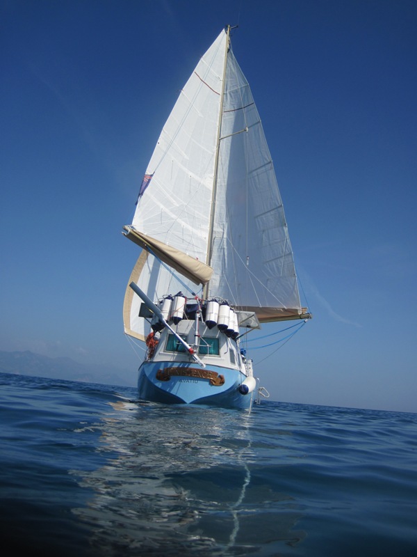
I make no excuses for showing every one of
these great pics of her, Ed. 'Existence' is an Atlantic
clipper prepared by victor and Olga and family over the course of several years
and sailed by them from their home in Serbia across the Mediterranean and then
across the Atlantic. the preparation for this trip can be viewed on
the Restorers pages, click here. We have just completed a check list for the
brokers here in the West Indies with the most full description of the boat.
The most wonderful thing about her is that she is
just ready to go right now, because we were preparing her for ourselves and
did not yet use even a fraction of her potential. That's why, as we've
mentioned, we don't want to leave her unattended for a long time, because
everything that is new today, will not be that new in some years. She has to
sail on!
SOLD Hello John
3/15 April 2017. We have just heard from Andrew in Florida that he is the new owner. He has just joined us, and the Forum!
He has sent an intriguing enquiry.. have the keel bolts been replaced? Had to refer him to this page and there is no mention of this. Then I had a thought. Does the Atlantic Clipper, (or the Barbican, come to that..) have an external ballast keel?? Many production GRP boats have internal encapsulated ballast. And the only fastening are normally bonded in studs that are then secured to frames or other strong structures within the boat to assist supporting the weight. So what do Atlantic Clippers have? anyone let us know.... John
|